Apc Tachometer Wiring Diagram

2 Pool Spa Filter Utility Pressure Gauge For Water Oil Https

Pin On Gauges Car And Truck Parts

10 Case Ih Cx100 Engine Wiring Diagram Engine Diagram In 2020

Connecting Pin Female Hdmi Connector

Universal Simple Wiring Diagram Do The Ton

97 Harley Davidson Radio Wiring Diagram C3 Wiring Diagram
Installation points tach learning to learn the tach signal.
Apc tachometer wiring diagram. For chrysler blue gold and silver boxes ford standard electronic ignitions and most other oem standard. This tachometer is factory calibrated for 8 cylinder engines. A switched 12 or 24 volt wire can be found coming from the ignition switch. September 7 2018 by larry a.
Figure a figure b 1965 impalla wiring diagram. Use plug in connector kit p n 0174732 when installing tachometer only. Figure a figure b 1967 chevy ac assembly manual drawing a 1968 camero wiring in a pdf file. This is a short video on a quick method of using any amc car to test a tachometer.
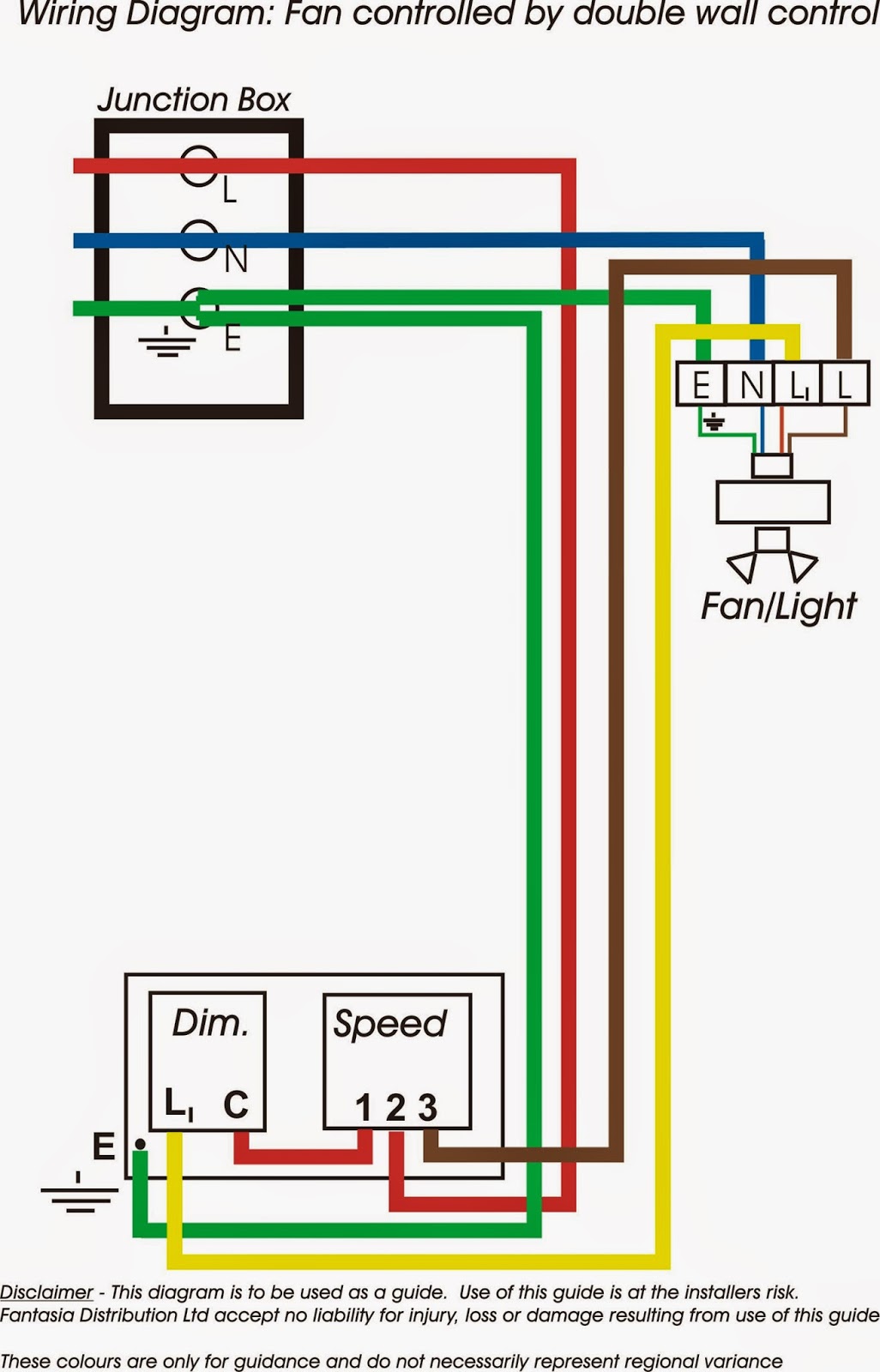
Variety of autometer tach wiring diagram. Connect the wire from pin 4 to a switched 12 volt or 24 volt source. Use a wiring kit to connect the tachometer to the plug in connector on the remote control or accessory electrical cable. It contains directions and diagrams for various varieties of wiring strategies along with other things like lights windows etc.
Circuit diagram of generation one and two smiths tachometer as used tachometer wiring excerpt of gt diagram tach wiring is. By way of a loop of wire in series with the ignition coil attached to the rear of the case. Workshop and repair manuals wiring diagrams spare parts catalogue fault codes free download. 2 violet white tachometer input wire 3 brown brake shutdown input wire 4 gray hood pin switch shutdown wire 5 blue white 200 ma 2nd status rear defogger important.
Wiring connect the tachometer wires as shown. The linked images are printable but may print across more than 1 page in order to be legible. Connect a wire from pin 5 to a constant 12 or 24 volt source. It reveals the components of the circuit as simplified shapes and also the power and also signal connections in between the devices.
Never connect a 200ma low current output directly to a motor or high current device without a relay. Follow this wire to a junction and attach the wire from pin 4 at this junction i e. For operation on 4 or 6 cylinder engines a switch adjustment must be made. Use plug in fuse block kit p n 0173611 when installing tachometer with other accessories.
Figure a figure b 1965 chevy ii wiring diagram. Refer to diagram d. Auto gauge tach wiring wiring diagram data autometer gauge wiring diagram wiring diagram consists of numerous in depth illustrations that show the connection of varied items. The wiring diagram shown is a typical installation.
A wiring diagram is a streamlined standard pictorial representation of an electrical circuit.

Power Acoustik Gt 202 Wiring Diagram Diagram Base Website Wiring
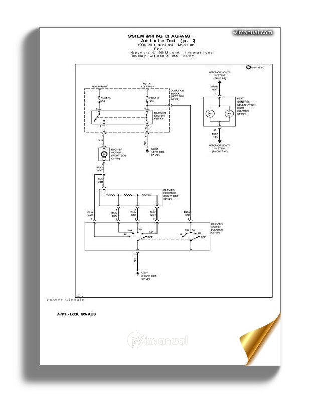
Mitsubishi Pajero Electrical Wiring Diagrams 1991 1999 Download

Otherpic Dogxl160 Ebike Jpg

Ir Receivercircuit Electroniccircuits

Pin On Biblioteca

Pin On Arduino Project

Arduvision Ii Ov7670 Fifo Module And Arduino Mega Electronics

Thermotec 14620 60 X 36 Heat And Sound Suppressor Want

Ultrastart U1272 Pro Remote Car Starter Keyless Entry Combo With

Connecting Pin Female Hdmi Connector
M55 Wiring Diagram Diagram Base Website Wiring Diagram

74 Corvette Wiring Diagram Diagram Base Website Wiring Diagram
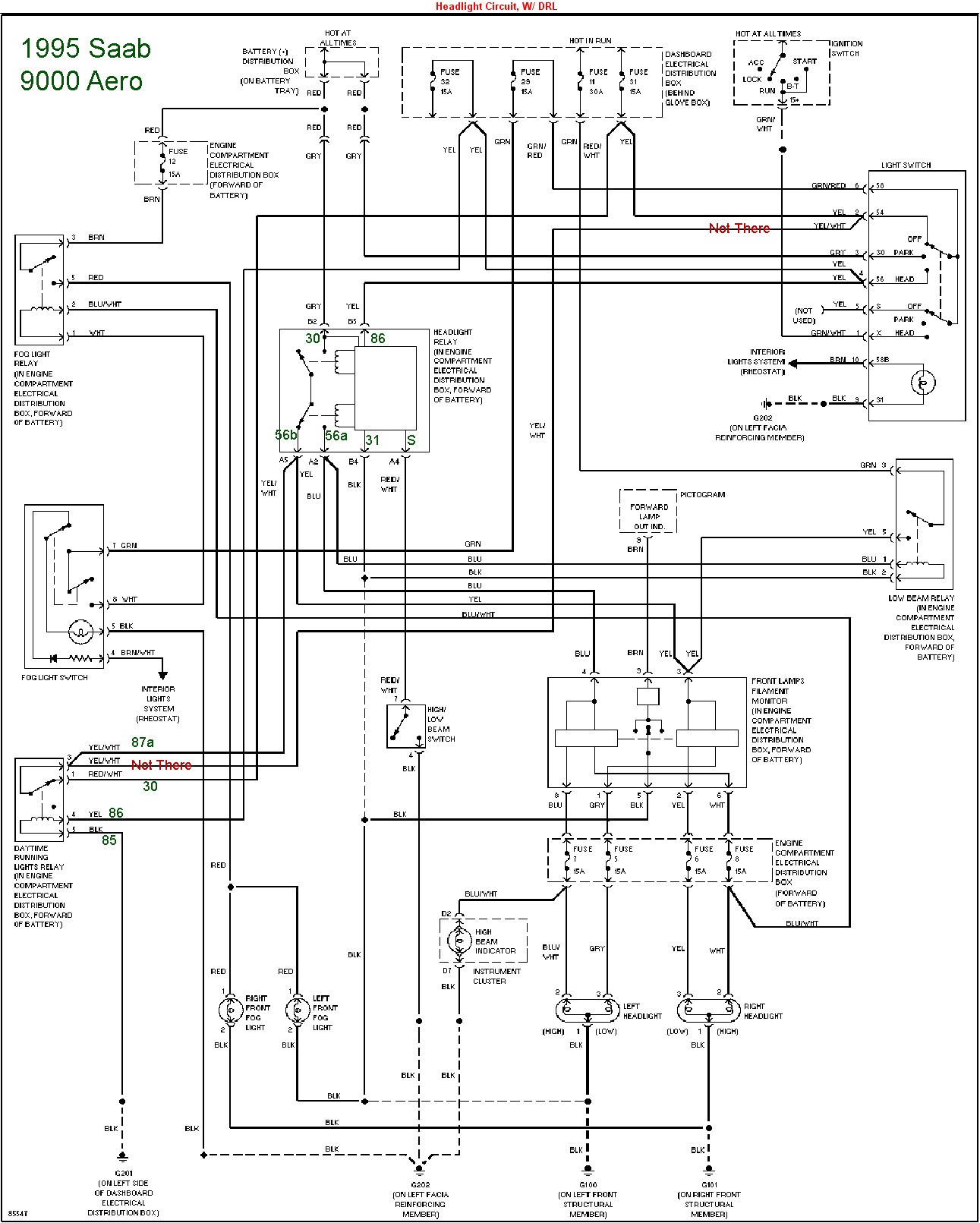
2003 Saab 9 3 Stereo Wiring Diagram Diagram Base Website Wiring
